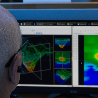
Visualizer 3D StudioAnalyzing and Editing 3D Scan Images
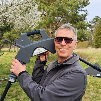
Before conducting any geophysical measurement you have to know what kind of objects or cavities you are looking for and if the area you choose is suitable for this procedure. Measuring without a plan will not give you the results you are expecting.
Prior to performing a scan, ensure that you have chosen a suitable site where you believe an item to be. Blindly searching an area may produce undesired results. For this reason, please note the following instructions:
- What are you looking for (graves, tunnels, buried objects, ...)? If you are looking for big objects you can enlarge your distance between the impulses (measuring points), for small objects use smaller distances.
- Inform yourself about the area you choose for measurement. Is it useful to search at this place? Are there historical indications, which confirm your speculations? What type of soil is present at this area? Are there good conditions? Is correct data recording possible?
- Your first measurement in an unknown area has to be large enough to get representative scan values (e.g. 40 impulses, 20 scan lines).
- What is the expected shape of the object you are going to detect? If you are looking for an angular metal box, the identified object in your scan image should have a form according to your expectations.
- To get precise scan values concerning the depth measurement, the object has to be in the center of the scan image, which means it has to be surrounded by normal reference values (normal ground). If the object is at the side of the scan image and not totally visible a correct depth measurement is not possible.
- If possible there should be only one single object in your scan image. Otherwise, this will influence the correctness of the depth measurement.
- You should do at least two control scans to make sure your results are valid. So you can also recognize and isolate mineralized ground.
After conducting the geophysical measurement according to the previous hints and our Ground Scan Guide, the recorded scan data needs to be analyzed. In the following sections all necessary information concerning 3D scan analysis will be provided.
Proper data analysis is necessary when working with any geophysical instrument. Properly configuring the software as well as taking in all necessary factors of the terrain is important to the analysis of the given information.
Looking at the graphic for the first time
Think about what it is that you are looking for. Are you looking for a tunnel? Did you do the right kind of scan to detect a tunnel?
When you are looking for a metal chest or steel box, the first sign on the scan should be a red or orange area that is isolated. If you are looking for a tunnel the scan must be much larger and you will be looking for a blue area, and these color differences are usually very strong from one to the other. Generally speaking, one needs to look at all the colors and also the shapes. Because the unit does work with the naturally occurring magnetic fields, the poles may actually reverse so red is blue and blue is red.
The final result from the given colors if it will be red or blue may lie on the following factors:
- Soil type (for example Loam, Sand, Rock, Concrete, ...)
- Scanning an area where there is a lot of debris (for example nails, trash, aluminum cans, construction debris, ...)
Color Definition
Under optimum conditions the colors can quickly assist you in finding and identifying the sub-surface object as well as what it is made of. There are occasions when the soil may have be more mineralized than in other areas. Normally speaking the colors mean:
- Blue colors normally are associated with voids, tunnels, cavities, water, disturbed earth and non-metallic items.
- Green colors typically refer to undisturbed soil. Soil that is “normal” so to say for it does not have extreme high amount of mineralized contents.
- Yellow and orange colors typically refer to areas where there are higher amounts of mineralized soil or can possibly be deeper metal objects. Many mixes of concrete also show up in the yellow and orange areas, especially that which is reinforced.
- Red colors are typically associated with metallic sub-surface targets. The red coloration means that a positive signal was received. On occasion areas with highly mineralized soil will also show many areas with red coloration.
As a note, an important element that can be quickly realized via the colors are metal objects made from iron, cobalt and nickel for they are very magnetic. These metals almost always will have a strong positive (red) pole and a strong negative (blue) pole.
Mineralized soil is also an important factor to take into consideration. We mentioned earlier in this manual about making control scans. When you scan an area for example three time over the same starting and stopping points, remember this basic rule, “Real Targets Don't Move!”. If in your second and third control scans you realize that nothing is staying in the same place, most likely there is nothing there and you are looking at a patch of mineralized soil.

In figure 1, a typical ferromagnetic signature is shown. It is not difficult to know the exact characteristics. The red and the blue directly next to one another is the key. Normally the colors will have approximately the same size and shape.
Recognizing the background color
When viewing a scan, try to see which color is dominant throughout. This is your background color that defines your "normal" soil. In standard soils, it will typically be green with some lighter and darker shades. There are conditions where the color may be completely different like blue. This may happen in different soil conditions that have stronger mineralized soils.
Search for anomalies
After you have established what the background color is, now it is time to look for the anomalies. If you see a distinct color difference this may be a possible anomaly. It will be very recognizable from the background whereas when rotating and viewing the suspect will be a large difference.
You can also view the scan from the side. At this point you will see that the difference is so great that you will have to zoom out in order to see the entire scan. This is a time when a control scan needs to be performed to ensure that there weren't any errors made in the first scan. As is often stated, it is important to remember that real targets do not move.
Now there is also the possibility that you have a scan that has a lot of different colors all at the same time. This usually occurs when one is looking at completely normal soil without any significant properties.
Void Interferences
There are outside forces which can cause interference to your signal. For example some of these interferences are caused by being too close to a radio station, bad weather including lightning, being too close to high powered electrical conduits, ground radar from an airport, high powered speakers and magnets to name a few. These errors you can see in your scan results. Normally these signal interferences can be quickly identified by a single strong spike within the scan often turning the entire scan a dark orange or red color. The signal can be corrected within the Visualizer 3D Studio software.
Position of an anomaly within a graphic
Should you find an anomaly, it is important to situate the anomaly within the middle of the scan and not on an edge. Also you must be able to differentiate it from the background color. This way you will be able to identify the exact location of the target.
If you find an anomaly only on the edge of a scan, change the size of your scan so that the area scanned is including the suspect area. Only when a target is directly in the center of a scan, can a proper analysis be made.
Metal object or mineralisation
At the very beginning it is not always easy to find out the difference between metallic objects and mineralization. Generally, metals are represented in reddish colors, but mineralized deposits in the ground can also include red color signals.
When you come across an area where you see darker oranges and reds in the scan, it is important to determine if it is indeed a metallic object or if the ground is highly mineralized. Naturally soils that are highly mineralized will quickly be known for all the scans in the area will show nearly the same.
For the beginner this can be very frustrating to decipher the difference. And there are even areas of soil which have high concentrations of iron that will show red. This is where the control scans are imperative, take care as to all of the details during a control scan to ensure that it is performed properly.
Here are some important notes how to distinguish a real object from a mineralization (please take note that the following information are based on the usage of the standard color scheme "Red-Green-Blue"):
-
Form or shape
Does the object have a recognizable shape (for example right angle edges, circle, etc...)? This is one of the biggest key factors to take into consideration. Can you repeat the scan with the same results? Is the anomaly more than on one point? When doing the analysis, is there more than one measure point to the object. If when going over the target with the cross hairs does the target only take one measure point? -
Color
Are there many reds, oranges and yellows in the scan? In the event there are, most likely that is mineralized soil and there is nothing there. Upon performing control scans, you will realize that the reds will move. -
Control Scans
Upon performing additional scans over a given area and the target does not move and the shape does not radically change, then you may be looking at a real target. When conducting a control scan be sure that your entire work area is clear from any unwanted debris. Using the “Magnetometer” now is a wise choice to ensure that there is not any unwanted debris. Also it is advisable when doing the scans to use the “Parallel” mode to lower the chance of error.
Please read section Modifiers to get more information about how to detect mineralization with the modifier functions!
Additional tools for Data Analysis in Visualizer 3D Studio
The Right Sidebar of Visualizer 3D Studio offers various options that help to analyze and optimize your scan images.
 |
Soil Types Applying the proper soil type is one of the essential keys to determine the correct depth of potential objects. Read more ... |
 |
Scan Information / Characteristics Another important step is to apply information regarding the scan field itself (e.g. field length and width). Read more ... |
 |
Bookmarks It might be helpful to set markers or bookmarks at special scan points to add important notes (e.g. for any PDF Report generation). Read more ... |
 |
Modifiers Special modifiers or mathematical algorithms can by applied to optimize and improve the collected scan data. Read more ... |
 |
Visualization Besides mathematical improvements that are changing the scan data directly, there are many options to improve the visual representation of the scan image without changing scan data. Read more ... |
 |
Transformations / Views |
In addition to the information in this documentation OKM offers individual training for Detectors and Software Analysis.