How to Get Best 3D Scan Images
Many users ask what their scans are showing. In fact, a successful analysis requires not only the ability to "read" the scan image properly, but also to create a good scan image. In this tutorial we explain how to get really good scan results with OKM ground scanners.
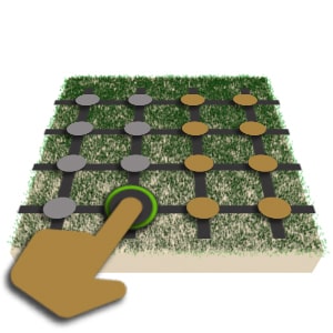
How to perform a Ground Scan (example with Rover C4):
How to achieve best Ground Scan images

Tip #1 – Orientation of the Probe
The correct position of the sensor guarantees good scan images: Make sure that you keep the probe straight while measuring!
Special Feature Orientation Sensor: The professional ground scanner eXp 6000 has an integrated orientation sensor that warns its user when the probe is held incorrectly.

Tip #2 – Direction of the Probe
The correct position of the sensor guarantees good scan images: Make sure that you do not pivot the probe while measuring! When using a vertical probe e.g. the Super Sensor, make sure that the arrow on top points in the direction of your scan line. Do not pivot or rotate the probe while performing ground scans.

Tip #3 – Distance to the Ground
Try to keep the probe always at the same distance above the ground surface during the scan (same distance as for ground balance before the measurement). If there are branches or stones in the scan field, lift the sensor higher for the ground balance to ensure a constant distance to the ground during the measurement.

Tip #4 – Direction of the Scan Lines
Experience shows that scans in north-south (or south-north) orientation produce better scan image results. If you can, follow the natural magnetic field of the earth when measuring, i.e. ideally perform your scan by walking your scan lines parallel to the meridians (longitudes).

Tip #5 – Preparation of the Scan Field
If you do not yet have a precise idea where to start measuring, it is often useful to first search the target area with the scan mode magnetometer. In this way first objects can be located and the ground can also be cleared from uninteresting objects such as ferrous waste. As a result, the subsequent Ground Scan can provide more informative results.

Tip #6 – Pace during the Measurement
For each scan line, walk slowly to collect enough measuring points (impulses) for a good scan image. The more measuring points are collected, the more detailed the scan image can be displayed. In this way, even smaller or hidden objects can be detected.

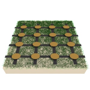
Tip #7 – Number of Scan Lines and Impulses
Reduce the distances between the measuring lines and/or scan more lines to collect enough measuring points (impulses) for a good scan image. The more measuring points are collected, the more detailed the scan image. In this way, even smaller or hidden objects can be detected.
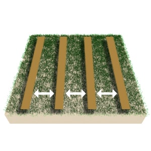
Tip #8 – Distance between Scan Lines
Try to scan the measuring lines always at the same distance to each other in order to obtain an accurate and correct scan image. In this way you avoid later analysis errors and do not miss small objects or objects hidden between the measuring lines.

Tip #9 – Constant Speed for all Scan Lines
If possible, always walk the scan lines at the same speed to obtain an accurate and correct scan image.
If a constant speed is not possible due to unevenness or obstacles in the scan field, it may be helpful to switch from automatic to manual impulse mode.
Tip #10 – Accuracy of the Measurement
Keep the measuring points (grid) as accurately as possible to obtain a correct and good scan image. This is easy to achieve by measuring each scan line always at the same speed and by keeping the distances between the lines always the same.
Tip #11 – Advantages of the Manual Mode
The manual mode can be particularly useful if there are larger obstacles in the scan field. If you have to climb over tree trunks or remnants of walls during the measurement or large undergrowth prevents you from walking at the same speed, you should try the manual mode. In this way the scan points (impulses) are not collected in the predefined speed, but only whenever you press the button on the probe / control unit. This ensures similar distances between the measuring points (grid).

Tip #12 – Advantages of the Parallel Scan Mode
Ground scans can be performed in two ways: parallel or zig-zag. Since it is important that the probe always points in the same direction, the parallel mode is especially recommended for beginners.
With parallel scan, the measurement is performed line by line always heading in the same direction. In this way the speed and the distances can be kept quite easily.
In zig-zag scan you either walk backwards - this can lead to errors in the measurement due to different walking speeds or deviations from the grid - or you turn on the spot, but the scanning direction of the probe must remain the same (then pointing to you).

Tip #13 – Adjustment of the Scan Field
Even if all instructions are followed, it is possible that the majority of the measuring field does not show any anomalies in the center, but reveals interesting signals at the edge of the field. If this is the case, move the measuring field so that the area of interest is located in the center of the scan field or that the boundaries of the target object can be identified.
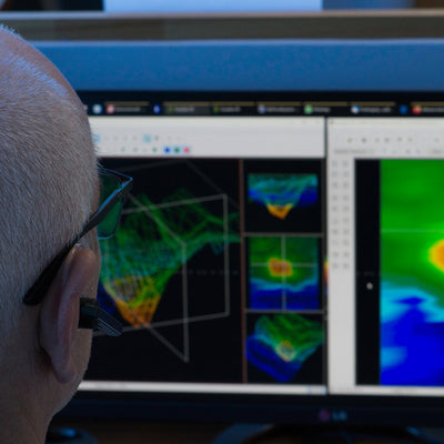
Check your Scan Data with a Control Scan
Once you have followed all the instructions and received a good scan image, check it with a second measurement. The so-called control scan is performed exactly like the first one: same scan field dimensions and same number of measurement points (impulses). If this control scan also shows the same patterns, you can be sure that the displayed anomalies are detected structures.
By the way: For each scan analysis by OKM a control scan is required. Beside the actual scan, the respective control scan has to be submitted in order to analyze the scan results as exactly as possible.
Download OKM 3D Ground Scan Guide
In our 3D Ground Scan Guide you find further details on how to use OKM ground scanners correctly to receive clear and meaningful scan images:
- Preparation of your Measurement
- Scanning Procedure
- Why Control Scans?
- Finalization of your 3D Ground Scan
- Major Rules for Measurements
- Expert Tips
Get the OKM 3D Ground Scan Guide (PDF, 1.1 MB):


Step-by-Step 3D Ground Scan Tutorial | OKM eXp 5500 Professional
Learn how to perform a 3D Ground Scan with the OKM eXp 5500 Professional. This step-by-step tutorial shows how to ...

Find Targets Faster with Pinpointer Mode | OKM eXp 7000 Tutorial
Learn how to locate targets faster and more precisely with the Pinpointer Mode of the OKM eXp 7000. This tutorial ...
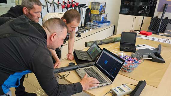
Scan Analyses, Hands-On Training & Sneak Peek at the OKM RoadShow in Sofia
Earlier this June, our experts hit the road – this time heading to Sofia, Bulgaria, for our OKM RoadShow. Together ...